320-Circuit Parallel Port Controller

Note: The information on this page is rather old and was never fully completed. Although this can technically still be built and used today, there are much better solutions available. This page is kept for historical reference only. If you are looking for an inexpensive DIY AC solution that also supports dimming, check out the Renard set of solutions.
Standard disclaimer: I’m not responsible for anyone hooking these circuits up and the results that follow their use.
After the 2001 season, I wasn’t sure how to expand beyond the original 8-port design. Luckily, I came across Hill Robertson’s design that can control up to 320 individual circuits. I modified it slightly, but it is really still the same design.
(Note: If you need a much smaller number of circuits, check out the original 8-port design. These can always be converted to work with this design with little effort.)
The Parallel Port
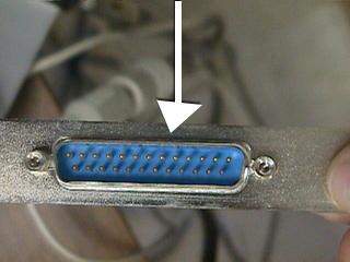
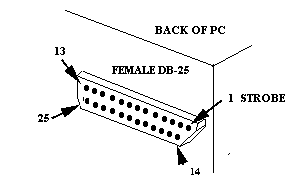
The parallel port was a great way to interface a PC to external devices because (at the time) every PC has one, and it’s easy to program. The parallel port has 8 output wires (OUTPUT), 5 input wires (STATUS), and 4 that are bi-directional (CONTROL).
| Pin | Label | Function | Type |
|---|---|---|---|
| 1 | C0 (~) | Strobe | Control |
| 2 | D0 | Data Bit 0 | Output |
| 3 | D1 | Data Bit 1 | Output |
| 4 | D2 | Data Bit 2 | Output |
| 5 | D3 | Data Bit 3 | Output |
| 6 | D4 | Data Bit 4 | Output |
| 7 | D5 | Data Bit 5 | Output |
| 8 | D6 | Data Bit 6 | Output |
| 9 | D7 | Data Bit 7 | Output |
| 10 | S6 | Acknowledge | Status |
| 11 | S7 (~) | Busy | Status |
| 12 | S5 | PE: Paper Tray Empty | Status |
| 13 | S4 | Printer On-Line | Status |
| 14 | C1 (~) | Auto Linefeed After Carriage Return | Control |
| 15 | S3 | Printer Error | Status |
| 16 | C2 | Initialize Printer | Control |
| 17 | C3 (~) | Select/Deselect Printer | Control |
| 18–25 | — | Unused / Ground | — |
In “Standard” mode, both the 8 data bits and the 4 control bits work as latched output pins. This means all 12 bits stay “on” or “off” until they are set differently — making very simple circuits for controlling lights.
The control bits are always two positions above the base address of the parallel port. For example, if your parallel port is at port 888 (0x378 hex) then the control address is at 890 (0x37A hex). This means pins 2–8 are controlled by setting the 8 bits on port 888, while pins 1, 14, 16, 17 are attached to the lower 4 bits on port 890.
To calculate what number to write, add up the values for each bit you want on:
| Bit | 1 | 2 | 3 | 4 | 5 | 6 | 7 | 8 |
|---|---|---|---|---|---|---|---|---|
| Value | 1 | 2 | 4 | 8 | 16 | 32 | 64 | 128 |
Examples:
- To set Bits 1 and 2 to send voltage, and the others to not → 1 + 2 = 3.
- To set Bits 2, 4, and 6 to send voltage and the others to not → 2 + 8 + 32 = 42.
The Design
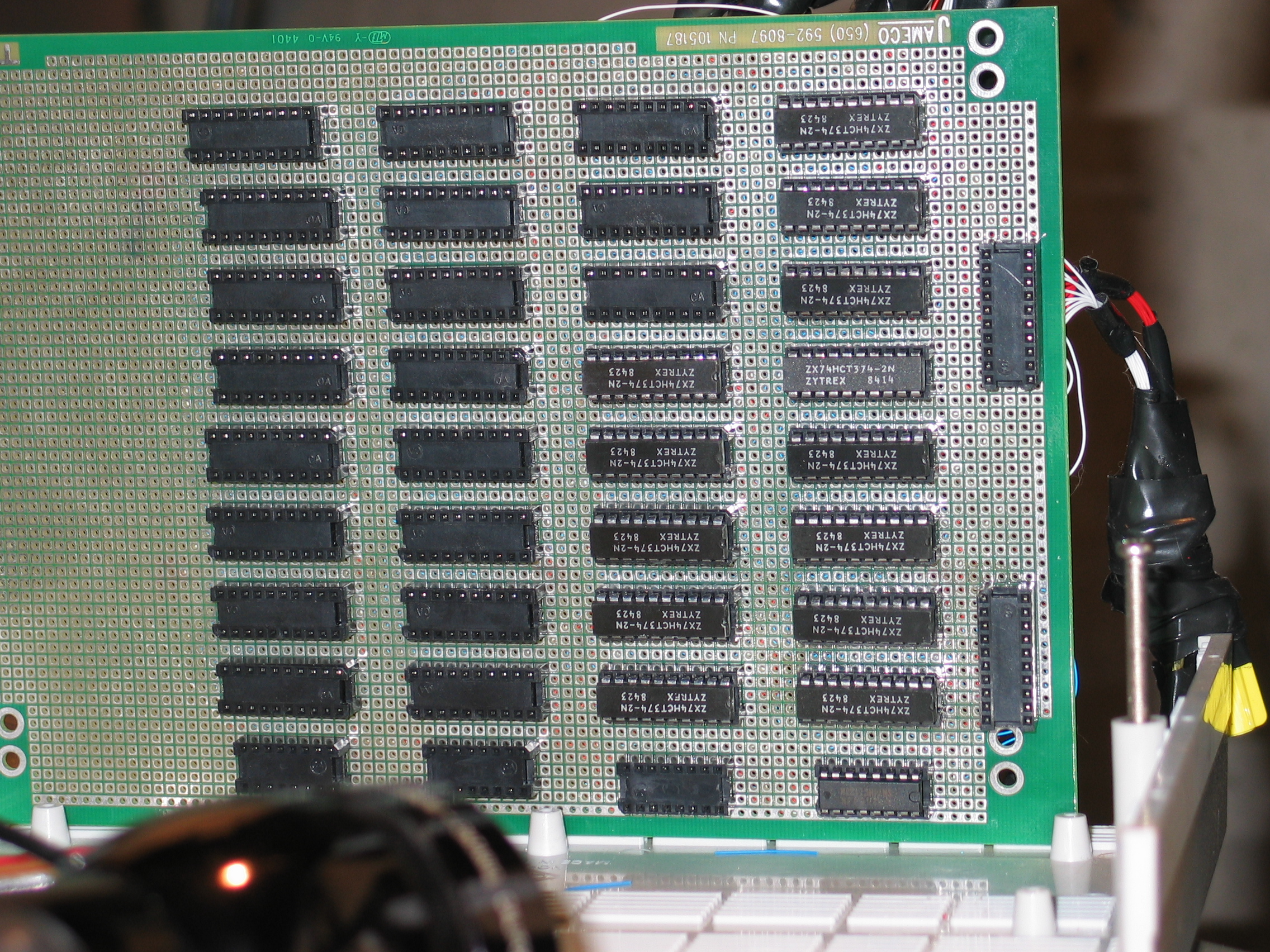
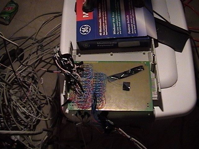
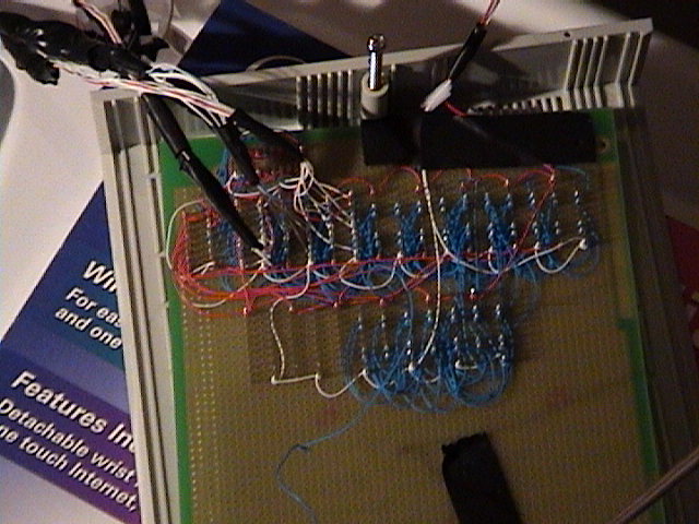
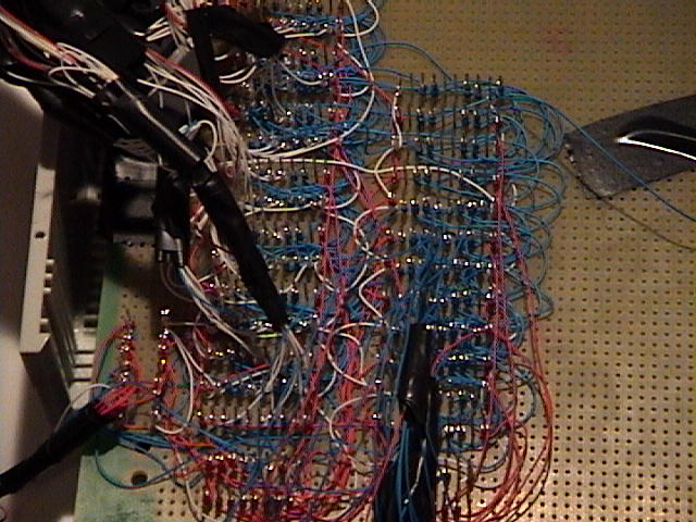
My design consists of 40 8-circuit boxes for a total of 320 individually switchable circuits. It requires 6 writes (6 clock cycles) to change a single box (or 240 to change all boxes). Even a very slow Pentium 75 is able to change all 40 boxes in the blink of an eye.
The design for the main board only requires two types of integrated circuits: the 138 decoder and the 374 flip-flop.
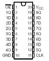
The 374 Flip-Flop is really just a single chip with 8 bits of memory. There are eight “D” pins representing the input and 8 “Q” pins that are the output. The chip works by continuing to output on the “Q” pins whatever was present on the corresponding “D” pin when a clock signal was received (a clock signal occurs when pin 1 goes from Low to High).
The 138 Decoder takes the binary representation of 3 bits (zero = 000, 7 = 111) and sets the output pin that matches that value to Low. For example, if pins 1–3 are given 010, then pin 12 (Y3) will be set Low, and all other Y pins will be set to High.
How a Write Works
- The first data byte (8 bits) is put into a temporary 374 “memory buffer” representing which of 8 AC circuits should be on or off.
- The flip-flop control bit (pin 1) is set low (0V — inverted), latching the data in the flip-flop. This allows us to use the 8-bits on the parallel port to set routing information next.
- The flip-flop control bit is set back to high (+5V), resetting it for next time.
- Routing information is sent via the normal data channel. 3 bits go to all 138 decoders specifying the “column”, while 5 other bits only go to one decoder specifying the “row”. (8 columns × 5 rows = 40 different 374 “memory” chips, each storing 8 bits = 320 unique outputs.)
- The decoder control bit (pin 14) is set high to send a clock (Low) to the specific flip-flop box, locking the data.
- Finally, the destination flip-flop latches the data and turns on or off the lights via the 8-circuit boxes, holding its state until the next instruction changes it.
Photos
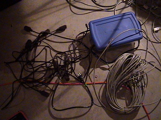
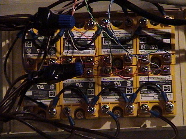
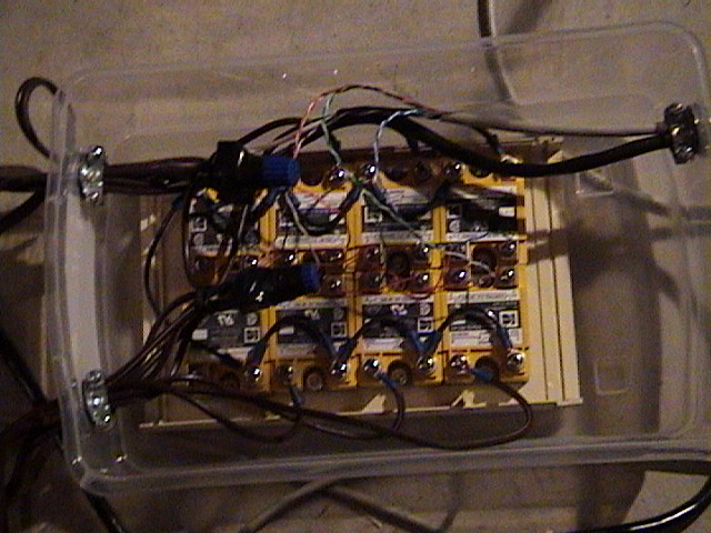


Seasons featuring this
Years where 320-Circuit Parallel Port Controller shows up in the display write-up.