8-Port Parallel Port Controller
Note: The information on this page is extremely old. Although this can technically still be done today, there are much better solutions available now. This page is kept for historical reference only.
There are multiple ways to control Christmas lights via a computer. If you are just getting started, using the parallel port is a good starting point. With just a little bit of electrical knowledge and some fairly common equipment, you can control up to 8 circuits per parallel port (max of 3 ports per computer) without needing to know anything about integrated circuits. Plus, if you plan to upgrade to a more complex parallel port control method (or use digital I/O boards), all you need to do is change out the 5Vdc interface and these boxes are ready to go in your new environment.
The Parts
| Item | Description | Cost |
|---|---|---|
| Solid State Relays (SSRs) | 10A 120V Relays. You can usually find them for $3–$10 used. You’ll need 8 of them. | $40 |
| Bulk Wire (14 gauge) | 5 feet of black, 5 feet of white | $1 |
| 14-3 Wire (rubber coated preferred) | 10ft or less | $6 |
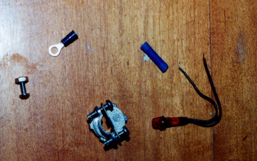
| Pig Tail (14 gauge) | Don’t go smaller than 14 gauge | $3 |
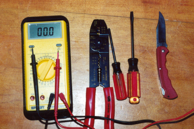
| Crimp Connectors | Optional, but preferred over wrapping wires | $5 |
| Machine Bolts with nuts | For connecting SSRs to project box | $5 |
| 120V Indicator (optional) | For debugging — 8 wired to electrical plugs | $8 |
| ½” Wire clamps | 5–10 pieces | $6 |
| Two 4×4 electrical boxes | Metal preferred | $8 |
| 4 outlets | Any color | $4 |
| Box to hold the SSRs | Project box | $12 |
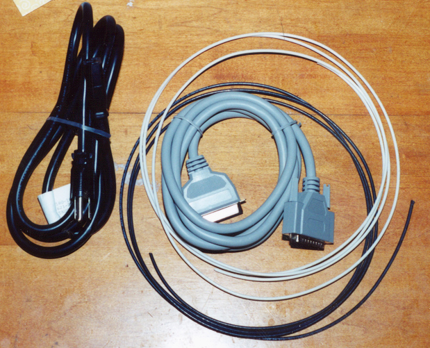
| DB-25 Wire | For parallel port connection | $5 |
| Total | ~$100 |
Standard disclaimer: I’m not responsible for anyone hooking these circuits up and the results that follow their use.
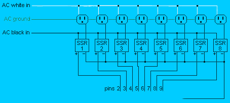
Schematic
Pins 2–9 are the control (positive) wires going to the box, while pins 18–25 can all be used for grounding.
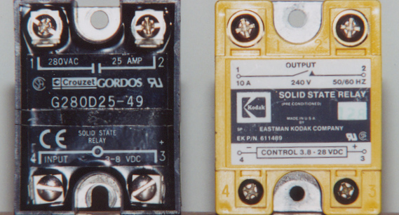
Solid State Relays
Solid State Relays (SSRs) are the heart of Parallel Port Control Boxes. All a Solid State Relay really does is allow the 110V AC current to pass through when 3–8V DC is applied, and opens the AC circuit when the DC is not present. If you shop around, you can usually find used 110V 10A SSRs that work with 5V DC input for under $5 a piece.
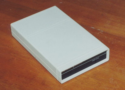
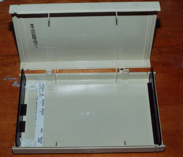
Relay Boxes
You’ll need a box (plastic or metal) to hold your eight solid state relays.
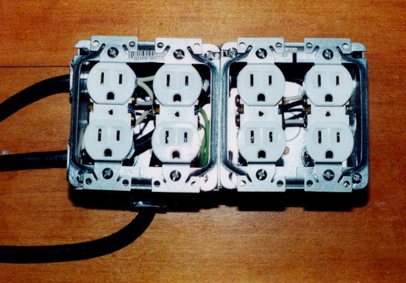
Electrical Boxes
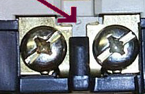
You’ll need an electrical box or two to hold your outlets. The NEUTRAL (right side) of each outlet should be connected together — do not break the tab on the neutral side. Since we want each outlet controlled individually, the tab on the hot (left side) IS broken.
14-3 rubber-coated wire is recommended because:
- The wire is very flexible and easier to work with than 14-3 solid wire
- Each wire (Black, White, and Green) is covered
- Bringing in 3 sets of coated wire provides 9 individual wires — exactly what’s needed to control 8 outlets (8 hot wires + one common ground)
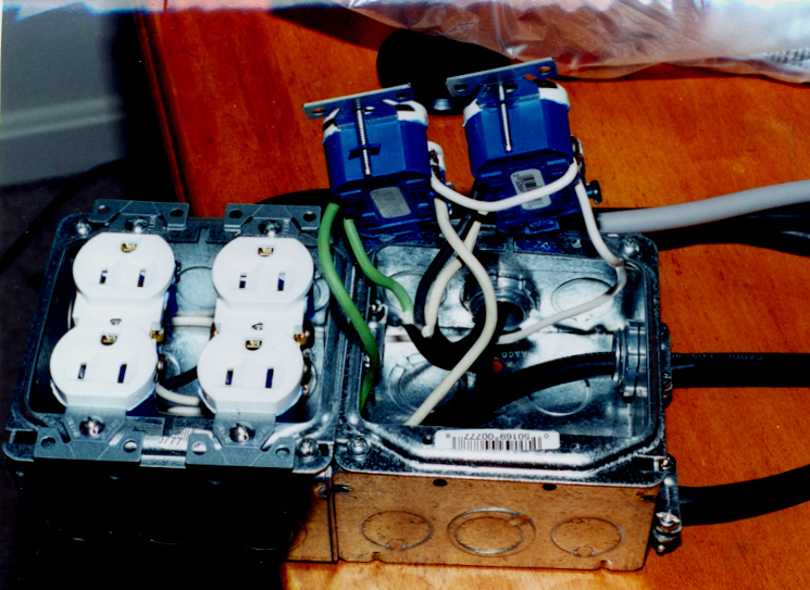
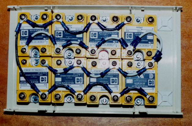
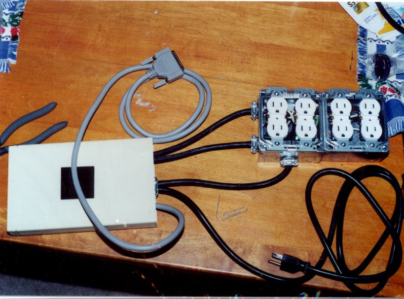
The Wired Relay Box
When wiring the relays into the box, the NEUTRAL terminals of the low voltage side can all be wired together (white wire). The incoming terminals of the 110V AC sides can all be wired together too (black wire) — this way 110V is available at each SSR, ready to be switched on.
If you want to include indicator lights in your boxes, get 120V indicators and connect them across the 120V AC side of your SSR. This is better than using a low-voltage LED because (1) the indicator won’t light if the SSR burns out, and (2) you aren’t pulling amps from the computer’s power supply to power the indicators.
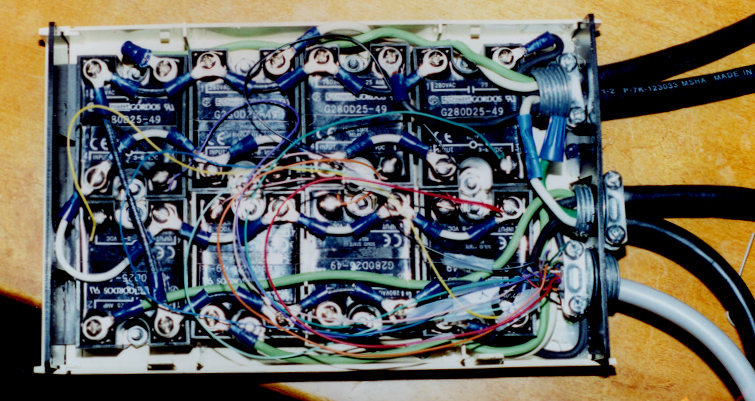
The Control Wires
Take a printer cable and cut off the printer end. Pins 2–9 on the parallel port cable should go to the individual SSRs (HOT side) and the ground wire (usually black with white stripe) should connect to the NEUTRAL side of the SSRs.
Controlling the Interface
If you are not interested in rolling your own software, check out Vixen. The Basic Parallel plug-in works just fine with this design.
Controlling the parallel port interface is really easy. Each of the 8 bits controls a circuit. Each bit has a value (bit 1=1, bit 2=2, bit 3=4, bit 4=8, bit 5=16, bit 6=32, bit 7=64, bit 8=128). The I/O address for the parallel port is normally 0x378 (888 in base 10). To turn on bits 3, 4, and 6:
out 888, 44 '4+8+32 = 44Sample QBasic code for random patterns:
'Parallel port 1 is port 888
'Each bit is a circuit
'out 888, 0 = all off
'out 888, 4 = #3 on
'out 888, 3 = #1,#2 on

randomize timer
Defint A-Z
A=0

do
   out 888, A  'Reset lights
   A = 256*RND 'Random sequence
   delay 1     'Wait 1 second
loop            'Loop back
Note: New versions of Windows (> 3.1) don’t allow direct control of the parallel port just by writing to the memory address. For Windows 95/98, boot into DOS mode. For Windows NT/2000/XP, controlling the parallel port is even more difficult. A DOS 5.0 boot disk is recommended for initial testing.
Photos